I’ve been in a tinkering mood lately but couldn’t settle on a good project. Finally one came to mind that I have been wanting to do for a while but never had the motivation for. My night vision is freaking awful, and we keep our bedroom incredibly dark to help my fiancee sleep, so when I wake up in the morning I usually end up bashing my knee into a few things and stepping on one of the various animals in the room. I want a way to easily turn on some lights in key areas, while also keeping most of the room dark to not wake up my fiancee. My chosen solution is an RF24 transceiver pair, one to act as the remote (with bonus mini light source), and the other to act as the light source. The remote will be able to turn the light on and off, as well as control the brightness of the LEDs.
Components
To follow along with this part, you will need the following components:
- 2 microcontrollers (I am using two Arduino Nanos for this)
- 2 RF24 transceivers
- 1 5KΩ potentiometer
- LEDs (I’m using NeoPixels, something like these)
- 2 slide switches
- Battery packs
- Breadboard
Transmitter
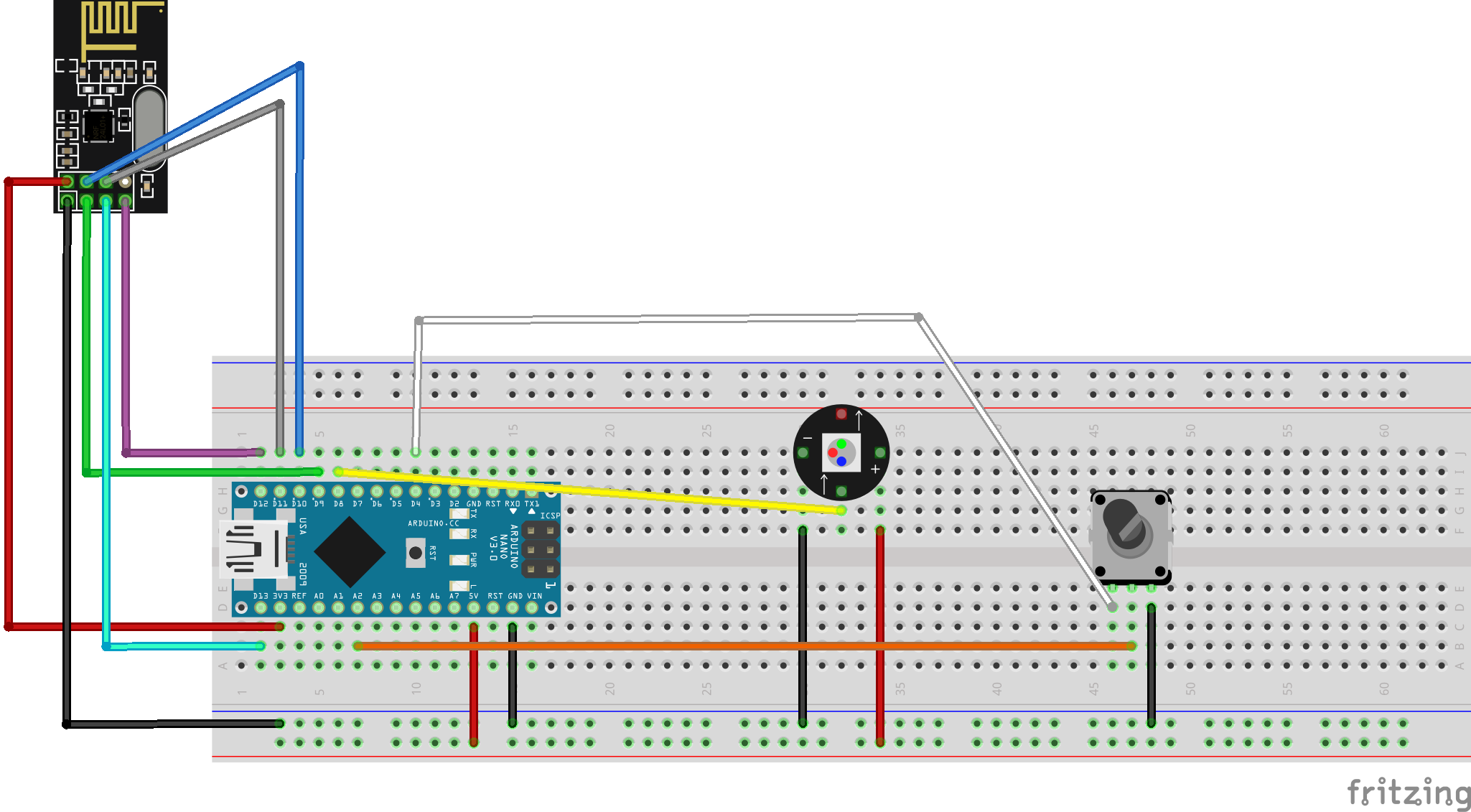
We are going to start with the transmitter, which will have a single LED for some minor directional light that I can use like a flashlight, and which will also have a potentiometer I can use to control the brightness of all of the LEDs around the room.
Wiring
Code
Alright so now we have an RF24 transceiver, an LED, and a potentiometer wired up. Make sure you have the proper libraries
installed. Using the Arduino IDE, you can use the Manage Libraries tool to find and
install the Adafruit Neopixel library and the RF24 library. If you would like to skip the explanations and go directly
to the full transmitter script, click here
Once we have that we can import all of our libraries:
#include <SPI.h>
#include <nRF24L01.h>
#include <RF24.h>
#include <Adafruit_NeoPixel.h>
#include "printf.h"
First we will initialize our single Neopixel. We only have 1, and we will use pin 8 as a control pin, so we can initialize it with this code:
Adafruit_NeoPixel pixels(1, 8, NEO_GRB + NEO_KHZ800);
Next we setup our RF24 transmitter. We have wired to pin 9 and 10 for the CE and CSN pins respectively, so we initialize like so:
RF24 radio(9, 10); // CE, CSN
const byte address[6] = "00001"; //Byte of array representing the address. This is the address where we will send the data. This should be same on the receiving side. 0x3130303030
Our address here is very important, we need to use the same value in the receiver in order for the two modules to
communicate properly.
Now we can setup our important global trackers:
int potPin = A2; // The pin tracking the potentiometer state
int powerPin = 4; // We set this to HIGH to give the potentiometer power
int brightness = 0; // Tracker for the current brightness
Now we are ready for our setup function. In our setup we need to do the following:
- Initialize the NeoPixel
- Send power to the potentiometer
- Initialize the Serial monitor for debugging
- Ensure the RF24 module is working
- Make the RF24 module a transmitter and set the payload size
void setup() {
   pixels.begin();
   Serial.begin(115200);
   digitalWrite(powerPin, HIGH);
   if (!radio.begin() || !radio.isChipConnected()) {
     Serial.println(F("radio hardware is not responding!!"));
     while (1) {} // hold in infinite loop
   }
   radio.openWritingPipe(address); //Setting the address where we will send the data
   radio.setPALevel(RF24_PA_LOW);  //Set minimum PA level since they will be close together
   radio.stopListening();          //This sets the module as transmitter
   radio.setPayloadSize(sizeof(brightness));

   // For debugging info
 //  printf_begin();             // needed only once for printing details
 //  radio.printPrettyDetails(); // function that prints human readable data
}
IMPORTANT: The setPayloadSize() function was required in order for my transceiver pair to actually work, for some
reason without it the receiver never picked up the payload.
Now in our loop all we have to do is check the current potentiometer setting and use that to set the brightness of our single NeoPixel as well as transmit the value so the other lights can use it. I used a 5KΩ potentiometer because it was pretty close to outputting values between 0 and 100 which is what the NeoPixel takes in as a brightness value. We will also add a check to only transmit if the brightness has actually changed.
void loop() {
  int potState = analogRead(potPin);
  bool brightnessChanged = brightness != potState;
  brightness = potState;
  pixels.setBrightness(brightness);
  pixels.setPixelColor(0, pixels.Color(255, 255, 255)); // Pixel is just set to white
  pixels.show();

  if (brightnessChanged) {
    unsigned long start_timer = micros();                    // start the timer
    bool report = radio.write(&brightness, sizeof(brightness));  //Sending the message to receiver
    unsigned long end_timer = micros();                      // end the timer

    if (report) {
      Serial.print(F("Transmission successful! "));          // payload was delivered
      Serial.print(F("Time to transmit = "));
      Serial.print(end_timer - start_timer);                 // print the timer result
      Serial.print(F(" us. Sent: "));
      Serial.println(brightness);
    } else {
      Serial.println(F("Transmission failed or timed out")); // payload was not delivered
    }
  }
  delay(300);
}
This works decently well, but we get a lot of voltage spikes if the potentiometer is not at one of the extremes of its arc. I could fix that by using a capacitor for voltage control, but I will tackle that later if at all. I don’t mind a bit of flickering in the light for now.
Receiver
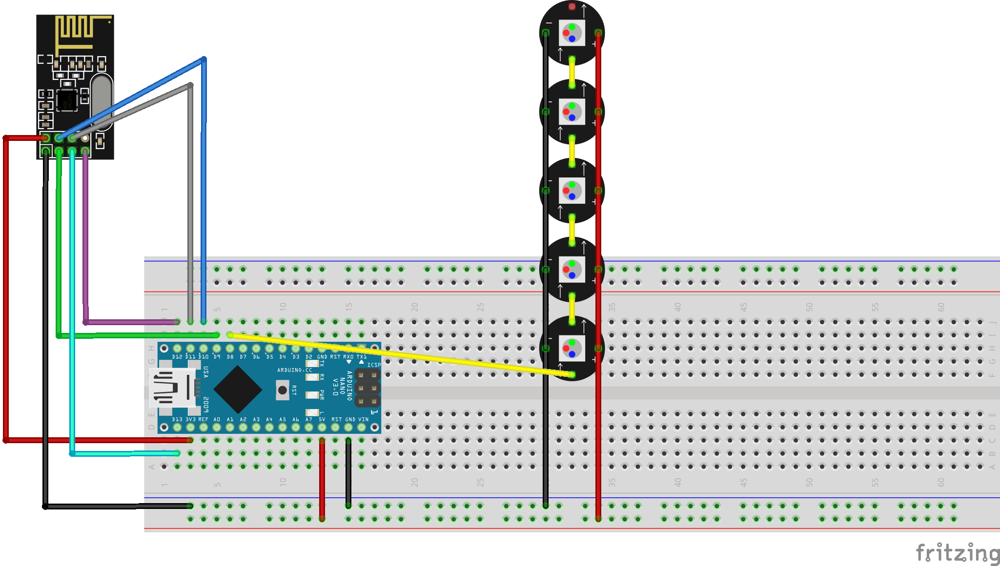
Wiring
Code
This code is very similar to the transmitter, so we include the same imports:
#include <SPI.h>
#include <nRF24L01.h>
#include <RF24.h>
#include <Adafruit_NeoPixel.h>
#include "printf.h"
And we have 5 NeoPixels for a strip rather than 1, so we initialize like this:
Adafruit_NeoPixel pixels(5, 8, NEO_GRB + NEO_KHZ800);
Now the main difference is that we set our transceiver to be in receive mode, and open a reading pipe in our setup:
int payload = 0;

RF24 radio(9, 10); // CE, CSN
const byte address[6] = "00001";     //Byte of array representing the address. This is the address where we will send the data. This should be same on the receiving side. 0x3130303030
void setup() {
  pixels.begin();
  Serial.begin(57600);
  // initialize the transceiver on the SPI bus
  if (!radio.begin() || !radio.isChipConnected()) {
    Serial.println(F("radio hardware is not responding!!"));
    while (1) {} // hold in infinite loop
  }
  radio.openReadingPipe(1, address); //Setting the address where we will receive the data
  radio.setPALevel(RF24_PA_LOW);     //You can set it as minimum or maximum depending on the distance between the transmitter and receiver.
  radio.startListening();            //This sets the module as receiver
  radio.setPayloadSize(sizeof(payload));

  // For debugging info
//   printf_begin();             // needed only once for printing details
//   radio.printPrettyDetails(); // (larger) function that prints human readable data
}
Then, in our loop, we just check if there is a message available and set our brightness in the LED strip appropriately:
void loop() {
  if (radio.available()) {             // is there a payload? get the pipe number that recieved it
    uint8_t bytes = radio.getPayloadSize(); // get the size of the payload
    radio.read(&payload, bytes);            // fetch payload from FIFO
    Serial.print(F("Received "));
    Serial.print(bytes);                    // print the size of the payload
    Serial.print(F(" bytes on pipe "));
    Serial.print(F(": "));
    Serial.println(payload);                // print the payload's value
    pixels.setBrightness(payload);
    pixels.setPixelColor(0, pixels.Color(255, 255, 255));
    pixels.setPixelColor(1, pixels.Color(255, 255, 255));
    pixels.setPixelColor(2, pixels.Color(255, 255, 255));
    pixels.setPixelColor(3, pixels.Color(255, 255, 255));
    pixels.setPixelColor(4, pixels.Color(255, 255, 255));
    pixels.show();
  } else {
    Serial.println(F("No payload"));
  }
  delay(300);
}
After we have all this uploaded and ready to go, when these boot up turning the potentiometer should increase the brightness for all LEDs.
Adding Battery Packs
For the remote and the LED strip, I want them to be battery powered. In order to power the Arduino, we need 3 AA batteries to give the 5V necessary to power the Arduino (actually more like 4.7V but it works). Now that we have the basic concept working, we can add battery packs to actually power the damn things, as well as power switches to save some battery power.
Wiring
It is pretty simple getting the Arduino to run on batteries, you just have to wire to the VIN pin and ground and you
are good to go.
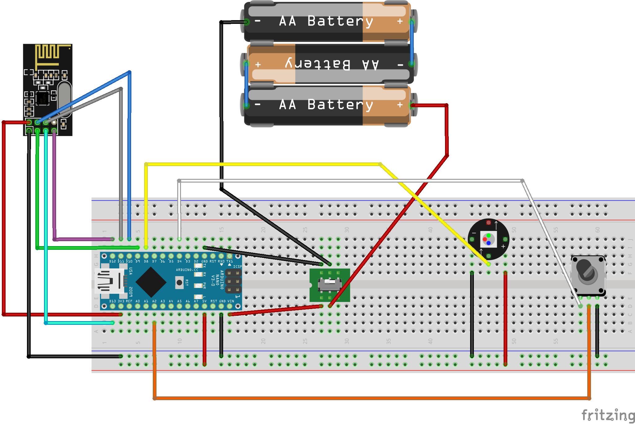
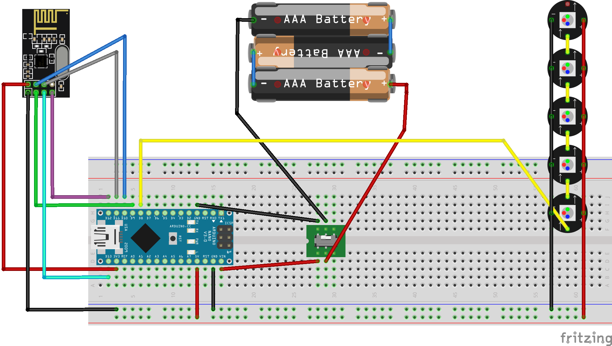
Once we have the batteries all wired up, when we flip the switch and move the potentiometer we finally get some lights!
Next Time
Now that we have the POC and all the code written, I want to make a remote and case out of wood so this stuff is actually usable. Stay tuned for the next installment where I make an inevitably terrible looking remote and LED strip case out of scrap wood. But hey, it will definitely work and that’s all I care about.
Full Code
Transmitter
#include <SPI.h>
#include <nRF24L01.h>
#include <RF24.h>
#include <Adafruit_NeoPixel.h>
#include "printf.h"

Adafruit_NeoPixel pixels(1, 8, NEO_GRB + NEO_KHZ800);

RF24 radio(9, 10); // CE, CSN
const byte address[6] = "00001"; //Byte of array representing the address. This is the address where we will send the data. This should be same on the receiving side. 0x3130303030
int potPin = A2; // The pin tracking the potentiometer state
int powerPin = 4; // We set this to HIGH to give the potentiometer power
int brightness = 0; // Tracker for the current brightness

void setup() {
  pixels.begin();
  Serial.begin(115200);
  digitalWrite(powerPin, HIGH);
  if (!radio.begin() || !radio.isChipConnected()) {
    Serial.println(F("radio hardware is not responding!!"));
    while (1) {} // hold in infinite loop
  }
  radio.openWritingPipe(address); //Setting the address where we will send the data
  radio.setPALevel(RF24_PA_LOW);  //You can set it as minimum or maximum depending on the distance between the transmitter and receiver.
  radio.stopListening();          //This sets the module as transmitter
  radio.setPayloadSize(sizeof(brightness));

  // For debugging info
//  printf_begin();             // needed only once for printing details
//  radio.printPrettyDetails(); // function that prints human readable data
}

void loop() {
  int potState = analogRead(potPin);
  bool brightnessChanged = brightness != potState;
  brightness = potState;
  pixels.setBrightness(brightness);
  pixels.setPixelColor(0, pixels.Color(255, 255, 255));
  pixels.show();

  if (brightnessChanged) {
    unsigned long start_timer = micros();                    // start the timer
    bool report = radio.write(&brightness, sizeof(brightness));  //Sending the message to receiver
    unsigned long end_timer = micros();                      // end the timer

    if (report) {
      Serial.print(F("Transmission successful! "));          // payload was delivered
      Serial.print(F("Time to transmit = "));
      Serial.print(end_timer - start_timer);                 // print the timer result
      Serial.print(F(" us. Sent: "));
      Serial.println(brightness);
    } else {
      Serial.println(F("Transmission failed or timed out")); // payload was not delivered
    }
  }
  delay(300);
}
Receiver
#include <SPI.h>
#include <nRF24L01.h>
#include <RF24.h>
#include <Adafruit_NeoPixel.h>
#include "printf.h"

Adafruit_NeoPixel pixels(5, 8, NEO_GRB + NEO_KHZ800);

int payload = 0;

RF24 radio(9, 10); // CE, CSN
const byte address[6] = "00001";     //Byte of array representing the address. This is the address where we will send the data. This should be same on the receiving side. 0x3130303030
void setup() {
  pixels.begin();
  Serial.begin(57600);
  // initialize the transceiver on the SPI bus
  if (!radio.begin() || !radio.isChipConnected()) {
    Serial.println(F("radio hardware is not responding!!"));
    while (1) {} // hold in infinite loop
  }
  radio.openReadingPipe(1, address); //Setting the address where we will receive the data
  radio.setPALevel(RF24_PA_LOW);     //You can set it as minimum or maximum depending on the distance between the transmitter and receiver.
  radio.startListening();            //This sets the module as receiver
  radio.setPayloadSize(sizeof(payload));

  // For debugging info
//   printf_begin();             // needed only once for printing details
//   radio.printPrettyDetails(); // (larger) function that prints human readable data
}

void loop() {
  if (radio.available()) {             // is there a payload? get the pipe number that recieved it
    uint8_t bytes = radio.getPayloadSize(); // get the size of the payload
    radio.read(&payload, bytes);            // fetch payload from FIFO
    Serial.print(F("Received "));
    Serial.print(bytes);                    // print the size of the payload
    Serial.print(F(" bytes on pipe "));
    Serial.print(F(": "));
    Serial.println(payload);                // print the payload's value
    pixels.setBrightness(payload);
    pixels.setPixelColor(0, pixels.Color(255, 255, 255));
    pixels.setPixelColor(1, pixels.Color(255, 255, 255));
    pixels.setPixelColor(2, pixels.Color(255, 255, 255));
    pixels.setPixelColor(3, pixels.Color(255, 255, 255));
    pixels.setPixelColor(4, pixels.Color(255, 255, 255));
    pixels.show();
  } else {
    Serial.println(F("No payload"));
  }
  delay(300);
}